Flowmeters and System Solutions
Flowmeters and System solution.
Flowmeters and System Solutions
Flowmeters and System solution.
PRODUCTS
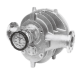
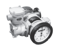
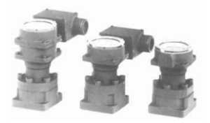
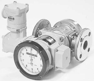
Format:PG30EP, PG30SEP, PG30DEP
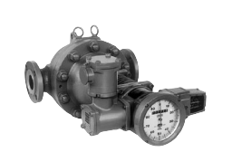
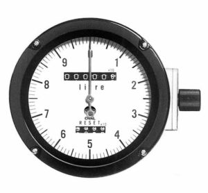
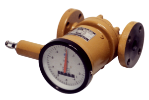
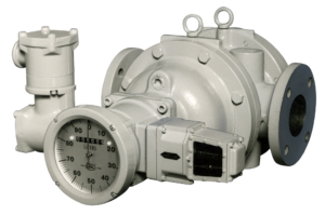
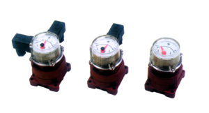
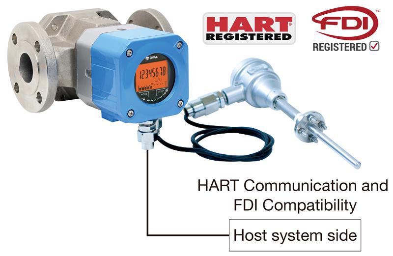
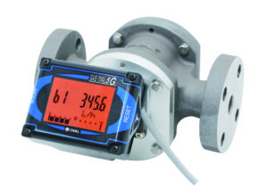
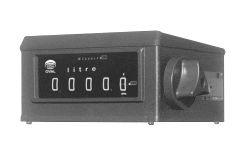
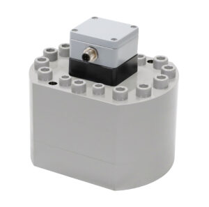
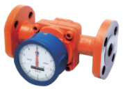
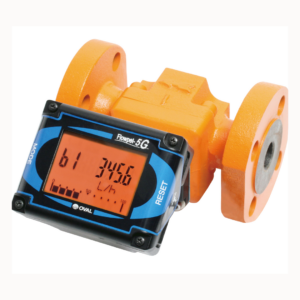
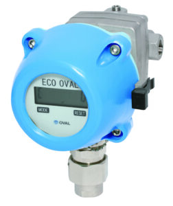
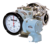
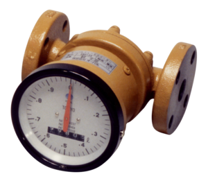
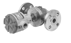
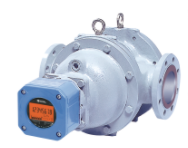
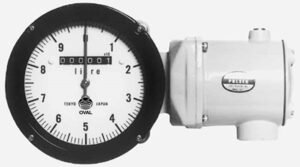
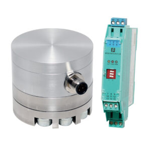
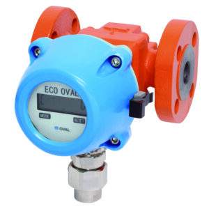
This pulse generator is designed to mount on an OVAL flowmeter or UF-II flowmeter and generates a frequency voltage pulse or current pulse signal proportional to the rate of flow. The signal generating element is entirely molded and contains a circuit to prevent stray pulse generation otherwise caused by vibation, thus making this pulse generator a highly reliable instrument. It comes in three designs, Models PG30EP, PG30SEP and PG30DEP. These are classified in the general specification on the next page. The flameproof configuration is designed and fabricated in accordance with the “Explosionproof Guidelines” recommended by established standards.
| Model | PG30SEP | PG30EP | PG30DEP | |||||
|---|---|---|---|---|---|---|---|---|
| Pulse output | Factored pulse output*1 | No. of pulses per one pointer rev. | 1P/rev | 10P/rev | 100P/rev | 1000P/rev | 100P/rev | 1000P/rev |
| Conversion gear ratio*2 | 1/10 | 1/1 | 2/1 | 20/1 | 2/1 | 20/1 | ||
| Unfactored pulse output*1 | Conversion gear ratio*2 | 1/1 | 2/1 | - | - | |||
| Principle of signal generation | RF OSC single-pulse detection (2-wire system) | RF OSC double-pulse detection (3-wire system) | RF OSC double-pulse detection (2-wire system) | |||||
| Explosionproof configuration | Flameproof construction, d2G4 | |||||||
| 防爆性能 | ||||||||
| Condit connection | G3/4 internal thread | |||||||
| Operating temp. range(Ta) | -10 to +65°C (at 95% RH) | |||||||
| No. og slots | 10s lits | 25 slits | ||||||
| Supply voltage(Ecc)*3 | 12VDC±10% ripple 100mVP-PMax. | 24VDC±10% ripple 100mVP-PMax. | ||||||
| Current drain(I) | 18mA Max. | 27mA Max. | 40mA Max. | |||||
| Load resistance(RL) | 510Ω±5%(receiver side) | 10kΩ Min. | 510Ω±5%(receiver side) | |||||
| Output signal | Reted range | “0”:3.3±0.3V,”1″:8.5±0.5V (Ecc=12VDC, RL=510Ω, Ta=20°C) |
“0”:0.5V Max.,”1″:6.9±0.5V (Ecc=12VDC, RL=10kΩ, Ta=20°C) |
“0”:6.5±1V,”1″:14±1V (Ecc=24VDC, RL=510Ω, Ta=20°C) |
||||
| Variation | “0”:3.3±1.5V, “1”:8.5±2.0V (Ecc=12VDC±10%, RL=510Ω±5%, Ta=-10 to +65°C) |
“0”:0.5V Max., “1”:6.9±0.7V (Ecc=12VDC±10%, RL=10kΩ、Ta=-10 to +65°C) |
“0”:6±2V, “1”:14.6±2V (Ecc=24VDC±10%, RL=510Ω±5%, Ta=-10 to +65°C) |
|||||
| Output waveform | Quasi-square wave | |||||||
| Pulse duty factor | Rated range | “0”/”1″=40/60 to 60/40 (Ecc=12VDC, RL=510Ω, Ta=20°C) |
“0”/”1″=30/70 to 60/40 (Ecc=12VDC, RL=10kΩ, Ta=20°C) |
“0”/”1″=30/70 to 60/40 (Ecc=24VDC, RL=510Ω, Ta=20°C) |
||||
| Variation | “0”/”1″=30/70 to 70/30 (Ecc=12VDC±10%, RL=510Ω±5%, Ta=-10 to +65°C) |
“0”/”1″=25/75 to 60/40 (Ecc=12VDC±10%, RL=10kΩ, Ta=-10 to +65°C) |
“0”/”1″=25/75 to 60/40 (Ecc=24VDC±10%, RL=510Ω±5%, Ta=-10 to +65°C) |
|||||
| Output frequency form | 5kHz Max. (across detector) | 2.5kHz Max. (across detector) | ||||||
| Transmission distance | 1km Max. | |||||||
| Suggested cable | 2-conductor shielded control cable (conductor area:1.25mm2Min., line resistance:20Ω/km Max., interconductor capacitance:0.2μF/km Max. | 3-conductor shielded control cable (conductor area:1.25mm2Min., line resistance:20Ω/km Max., interconductor capacitance:0.2μF/km Max. | 2-conductor shielded control cable (conductor area:1.25mm2Min., line resistance:20Ω/km Max., interconductor capacitance:0.2μF/km Max. | |||||
| Insulation resistance | Greater than 100MΩ (across terminals grouped and housing, by 500V DC Megger) | |||||||
| Withstand voltage | 500V AC for one minute across terminals grouped and housing | |||||||
| Vibration resistance | 3G Max. | |||||||
| Housing | Aluminum die casing | |||||||
| Mass, approx., kg | 2.5 | |||||||
*1:Factored pulse—for totalization. Unfactored pulse—for instantaneous flowrate indicator or flow controller.
*2:Conversion gear ratio is determined by full scale.
*3:OVAL DC powew supply unit is available.
*You need to fill out the questionnaire to download documents.
PG30, PG30EP, PG30D, PG30S, PG30SEP, PG30DEP