Flowmeters and System Solutions
Flowmeters and System solution.
Flowmeters and System Solutions
Flowmeters and System solution.
PRODUCTS
Format:LUS, LUJ, LCS, LBS, LQS
Liquid
Gas
Steam
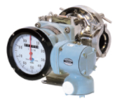
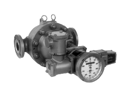
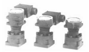
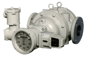
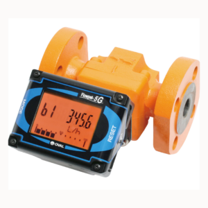
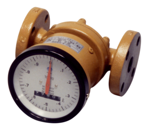
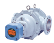
This device is a high-performance positive displacement flowmeter, which is a representative model of our positive displacement flowmeters
with HART communication and auto temperature compensator function in the counting section.
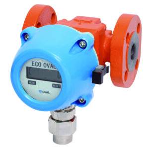
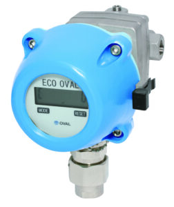
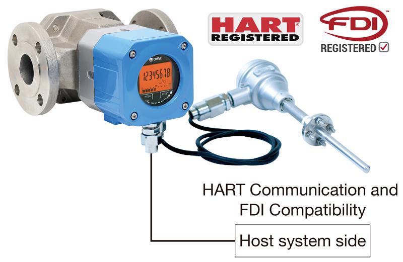
With HART communication, various monitoring and parameter settings are possible. Additionally, by measuring the fluid temperature with an externally connected temperature sensor, it continuously and automatically converts the measured flow temperature to the volumetric flow rate at a reference temperature (e.g., 15°C) for measurement.
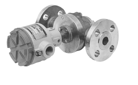
●Absence of mechanical reduction gear train combined with special carbon bushings contributes to low pressure loss and long life.
●Thanks to pocketless design, the process fluid is virtually free from stagnation in the measuring chamber beneficial to a broad range of fluids, particularly chemicals and foods.
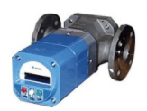
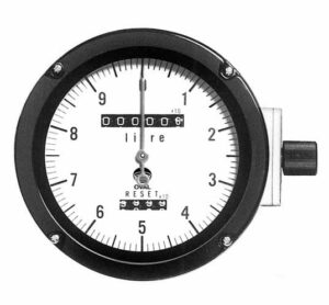
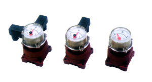
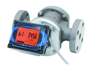
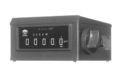
●The counting section allows for mode switching via touch operation, enabling LCD display of accumulated total, instantaneous flow rate, and reset total.
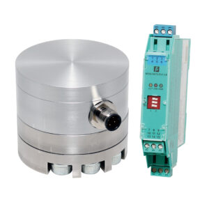
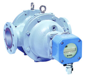
●External outputs can simultaneously output two systems of signals: accumulated signal (pulses) and instantaneous flow rate signal (analog).
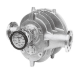
●Lineup includes explosion-proof specifications (pressure-resistant explosion-proof structure).
●We also manufacture models approved for applicable high-pressure gas control law.
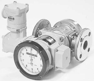
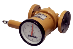
●By inserting a temperature sensor (resistance thermometer) connected to the register into the pipeline, accurate flow measurement is achieved while carrying out flowrate correction (volume conversion) of the process fluid to the reference temperature and temperature correction (3α) of the flowmeter body simultaneously.
●Compatible with HART communication, allowing for tasks such as remote verification of measurement values and loop checks.
water
gasoline
kerosene
light oil
heavy oil
paint
general chemical liquid
other
| Meter size | 39 | 41 | 45 | 50 | 52 | 53 | 55 | 56 | 57 | ||||||||
|---|---|---|---|---|---|---|---|---|---|---|---|---|---|---|---|---|---|
| Nominal size | 10mm(3/8″)(※1) | 20mm(3/4″)) | 25mm(1″) | 40mm(1・1/2″) | 50mm(2″) | ||||||||||||
| Flange rating | ・ 1 group JIS 10K RF、ASME/JPI 150 RF ・ 3 group JIS 16、20、30K RF、ASME/JPI300RF、DIN PN 10、16、20、25 |
||||||||||||||||
| Flow range | See flow range tables | ||||||||||||||||
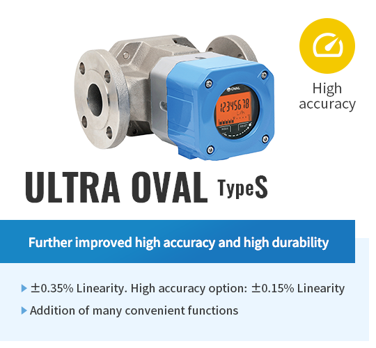
| Accuracy | ±0.35% or ±0.15% | ||||||||||||||||
| Operating temperature range | −10~+120℃(standard) | ||||||||||||||||
※1: 1/2″ for ASME and JPI flanged sensors.
● Meter sizes: 39 to 45 Linearity: ±0.35% Operating temp. range: –10 to +120°C
Unit: L/h
| Viscosity/ Meter size |
Less than 0.3mPa·s | 0.3mPa·s to 0.8mPa·s | 0.8mPa·s to 2mPa·s | 2mPa·s to 5mPa·s | 5mPa·s to ※200mPa·s | ||||
|---|---|---|---|---|---|---|---|---|---|
| 39 | 2 to 12 | 1.4 to 12 | 0.7 to 12 | 0.35 to 12 | 0.2 to 12 | ||||
| 41 | 18 to 60 | 12 to 60 | 4 to 60 | 2.5 to 60 | 1 to 60 | ||||
| 45 | 50 to 420 | 35 to 420 | 15 to 420 | 10 to 420 | 5 to 420 | ||||
※ Only model 45 can handle up to 1000mPa·s
● The standard linearity for model 39 is ±0.35%. Consult OVAL for ±0.15% linearity model.
● Meter sizes:50 to 57 Linearity: ±0.35% Operating temp. range: –10 to +120°C (std.)
Unit: m³/h
| Viscosity/ Meter size |
Less than 0.3mPa·s | 0.3mPa·s to 0.8mPa·s | 0.8mPa·s to 2mPa·s | 2mPa·s to 5mPa·s | 5mPa·s to 1000mPa·s | ||||
|---|---|---|---|---|---|---|---|---|---|
| 50 | 0.3 to 1.6 | 0.15 to 1.6 | 0.1 to 1.6 | 0.05 to 2 | 0.03 to 2 | ||||
| 52 | 0.7 to 3 | 0.4 to 3 | 0.3 to 3 | 0.15 to 3.8 | 0.08 to 3.8 | ||||
| 53 | 1.1 to 5 | 0.7 to 5 | 0.55 to 5 | 0.28 to 6.4 | 0.15 to 6.4 | ||||
| 55 | 1.8 to 11 | 1.2 to 11 | 1 to 11 | 0.4 to 14 | 0.26 to 14 | ||||
| 56 | 3.5 to 20 | 2.5 to 20 | 2 to 20 | 0.9 to 24 | 0.6 to 24 | ||||
| 57 | 8 to 37 | 5 to 37 | 4 to 37 | 2 to 44 | 1.2 to 44 | ||||
(Note) Accuracy: ±0.2% (optional) and for other flow range specifications, please refer to the applicable general specifications.
| Meter size | 39※ | 41 | 45※ | 50、52、53※ | 55、56、57※ | ||||
|---|---|---|---|---|---|---|---|---|---|
| Output | Analog, Pulse, Error | ||||||||
| Communication interface | HART protocol ※ HART 7 | ||||||||
| Backflow subtract function | Equipped (for the product with backflow subtract function only) | ||||||||
| Power supply | DC power or battery powered | ||||||||
| Transmission length | Power and signal cables: up to 1km (conductor cross-section area of 1.25mm²). Temperature sensor cable: up to 20m (conductor cross-section area of 0.89mm²). However, please install the temperature sensor in a close position where there is no significant temperature difference between the flowmeter body and the fluid temperature. |
||||||||
| Temperature input | The platinum sheath temperature sensor (Pt 100 Ω): JISC1604:2013, single element, and compatible with 3-wire connection. Temperature factored range: −10 to +150°C |
||||||||
| Calculation accuracy | Within ±0.1% of R.D. (excluding the accuracy of the temperature sensor (Pt100) | ||||||||
| Ambient temperature | –20 to +60°C (Without dew condensation) | ||||||||
| Explosionproof configuration | Flameproof enclosure configuration | ||||||||
| Degree of Protection for enclosure | IP66 | ||||||||
※: With factored pulse unit indicated with an asterisk ※, pulse width other than 1 ms is NOT selectable.
*You need to fill out the questionnaire to download documents.
39, 41, 45, 50, 52, 53, 55, 56, 57 (10 to 50mm)
29, 60, 31, 32, 33 (80 to 200mm/Single Case)
28, 29, 60, 31, 32, 33 (50 to 200mm/Double Case)
28, 29, 31, 32, 33 (50 to 200mm/Double case, Standard Jacketed)
34, 65 (250 to 350mm/Single Case)