Flowmeters and System Solutions
Flowmeters and System solution.
Flowmeters and System Solutions
Flowmeters and System solution.
PRODUCTS
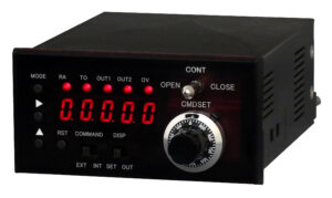
Format:ROU28C
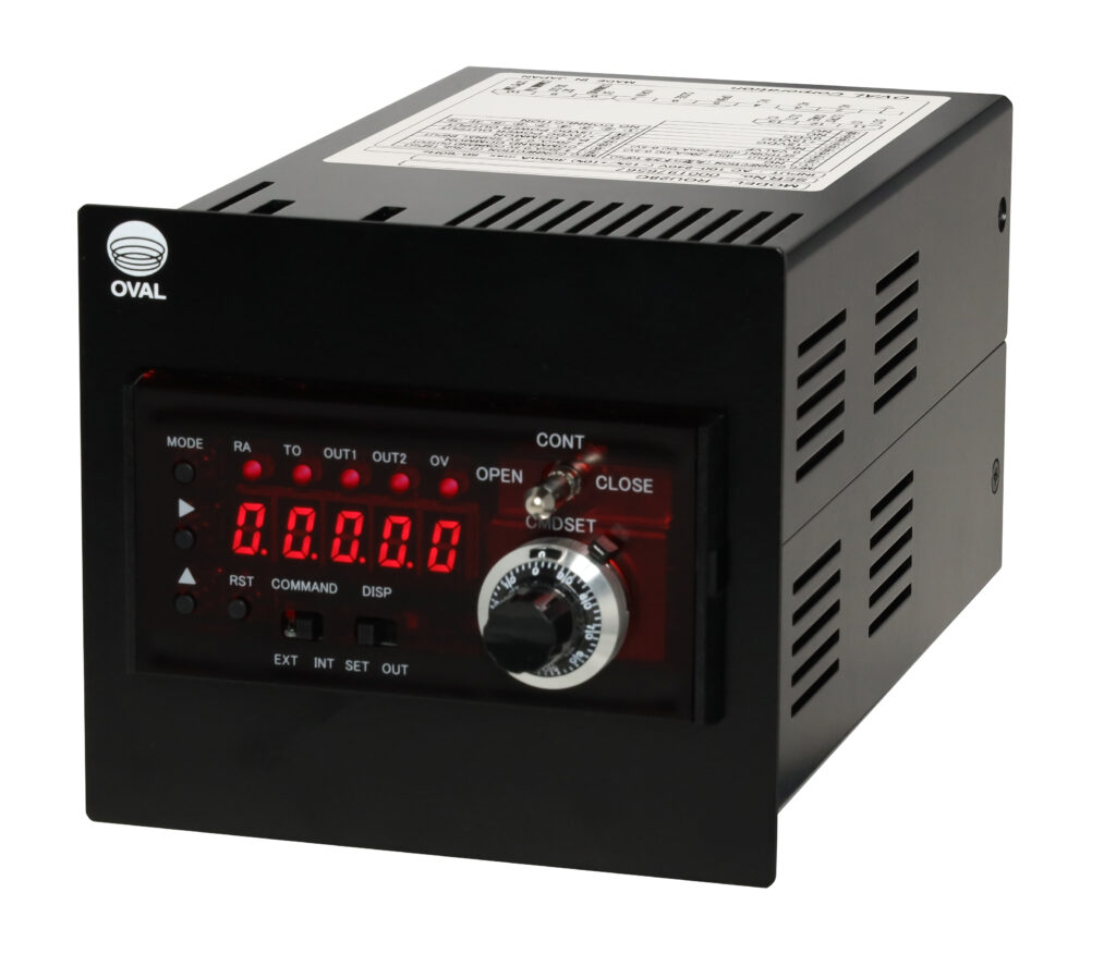
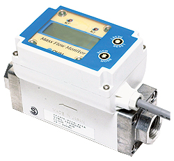
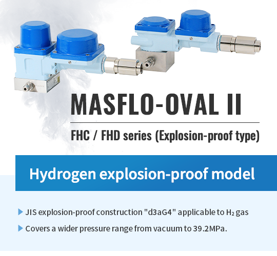
The ROU28S is a receiver designed for MASFLO-OVAL Ⅱ (thermal mass flowmeter/controller).
Functions necessary for flow measurement/control are integrated into specialized units.
The ROU28S enables the simple and cost-effective configuration of flow measurement/control systems.
●A small, lightweight receiving instrument with the basic functions required for measurement and control.
●Flow rate value, accumulated flowrate value and flowrate set-point can be switched to the display.
●A flow rate adjustment device and an external input switch are placed on the front, realizing an easy-to-use layout.
●As standard specifications, it includes external output (analog and pulse) and external control input functions.
Therefore, flexibility of system design can be improved.
●By combining the readout unit with the MASFLO-OVAL II series, a flow measurement system can be easily configured.
| Item | Specification | ||
|---|---|---|---|
| Measurement | Measurement types | Instantaneous flow rate value/total flow rate value | |
| Measurement method | A/D conversion method Resolution: Approximately 1/7000 (relative full-scale input) | ||
| Input measurement interval: approxinately 20ms | |||
| Low-cut | 0 to 29% of maximum analog input (can be set arbitrarily) | ||
| Display section | Display | Red LED 5-digit display Character height: 8mm (Zero-Blanking Method) | |
| Display switching | Switch between displaying flowrate value and accumulated value using the ▲ key (Requires setting in “Mode No.4”) ※When the DISP switch is set to OUT |
||
| RA lamp | Lights up (red) during flowrate value display | ||
| TO Lamp | Lights up (red) during accumulated value display | ||
| OV lamp | Lights up (red) when the displayed measurement value exceeds the range (During right-shifted display, it blinks) | ||
| OUT1 Lamp | Lights up during output of Alarm output OUT1 | ||
| OUT2 Lamp | ALights up during output of Alarm output OUT2 | ||
| Instantaneous value display | Measurement accuracy | ±0.3% (F.S.) ±1 digit (23°C) for analog input | |
| Scaling method | Arbitrary setting of instantaneous flowrate value display at maximum analog input (0.001 to 9999) | ||
| Display range | 0~ 9999 (When the display is over, “9999” flashes and the OV lamp lights up) | ||
| Decimal point display | Set at maximum display value (Mode No.1). | ||
| Display sampling time | Averaging the display in approximately 0.5 seconds (fixed) | ||
| Least significant digit correction | Averaging the display in approximately 0.5 seconds (fixed)Least Significant Digit Correction: Selectable from “Normal,” “0 fixed,” and “0 or 5” | ||
| Integrated value display | Measurement accuracy | ±0.3% (F.S.) ±1 digit (23℃) for analog input | |
| Scaling method | Arbitrary setting of accumulated value per hour at the maximum analog input value by mode setting | ||
| Display range | 0 to 9999 | ||
| Decimal point display | Selectable from 1 to 4 decimal places | ||
| Over (OV) display | When the displayed value exceeds 99999, it automatically shifts one digit to the right (continuing with right-shifted display). During right-shifted display, the OV Lamp blinks. If the display exceeds the x10 scale, the OV Lamp lights up and the display becomes endless. |
||
| Display offset | The integrated value after reset can be set to any value between 0 and 99999 by setting the display offset value. | ||
| Input signal | Flow signal | 4-20mADC [Initial setting value] or 0-5VDC (switched by DIP switch) Do not use D-sub connector and round connector at the same time. The equipment may be damaged. |
|
| External setting signal | 4-20mADC [Initial setting value] or 0-5VDC (switchable by dip switch) Terminal block 8-10 |
||
| Input resistance | 4-20mADC: approx. 250Ω 0-5VDC: approximately 330kΩ | ||
| VOR IN | Not used for MASFLO-OVAL II | ||
| Output related | Power supply rating | DC±15V 250mA each or DC+15V 150mA, DC-15V 350mA also supported Ripple noise: 30mV or less |
|
| Setting signal output | 4-20mADC [default setting] or 0-5VDC (switched by dip switch)
D-sub connector 5-6, circular connector 3-4 Do not use D-sub connector and circular connector at the same time This may damage the equipment |
||
| External signal output | 4-20mADC [default setting] or 0-5VDC (switchable by dip switch)
Terminal block 9-10 |
||
| Valve opening/closing output | Not used for MASFLO-OVAL II | ||
| Operation section | Mechanical dial (CMDSET) | Minimum scale of 10 rotary type potentiometer: 1/50 turns Equipped with a lock lever (to fix rotation and scale) (The scale on the dial serves as a reference for the amount of rotation) |
|
| Set to the flow rate you want to control | |||
| VOR switch | Not used for MASFLO-OVAL II. (CONT only) | ||
| Command switch (COMMAND) | EXT: The external setting value signal becomes the display for the flowrate setpoint. INT: The CMDSET mechanical dial (CMD) setting becomes the flowrate set-point display. |
||
| Display changeover switch (DISP) |
SET: Displays the flowrate set-point (relative to COMMAND). OUT: Displays the instantaneous and accumulated flowrate values |
||
| Operation setting switch | MODE, ▶, ▲, RST key switches | ||
| Alarm and synchronization output | Output terminal | Output from terminal blocks 11-12 (OUT1) and 13-12 (OUT2) (common to COM) | |
| Comparison method | Select from upper and lower limits | ||
| Output mode | Comparison/synchronization pulse max 40Hz (OUT1: Selectable via mode) | ||
| Preset value setting | Can be set arbitrarily in the preset value setting mode | ||
| Output judgment | Output determined by comparing the displayed value with the preset value | ||
| Output method | NPN open collector output, 2 points Maximum rating: DC30V, 50mA, MAX |
||
| Other | Data backup | Writes the setting values for each mode and accumulated measurement to FRAM (Rewriting limit: 100,000 times or less, approximately 10 years of retention |
|
| Mode protect function | Switching selection based on mode protect setting When “ON,” the set value cannot be changed; when “OFF,” the set value can be changed |
||
| Warm-up time | 30 minutes or more after power-on | ||
| Power supply | AC100-240V (-15% / +10%) 270mA max 50 / 60Hz Approx. 35VA or less | ||
| Operating temperature and humidity ranges | 0 to 50℃, 30 to 80%RH(without condensation) | ||
| Weight and outside dimensions | Approximately 1kg W114×H100×D217mm(without mounting bracket) | ||
| Main body color | Black | ||
| BOX material | Front part: SPCC
Other parts: Aluminum |
||
| Operating environment | Indoor use Maximum altitude 2,000m Overvoltage category II Pollution degree 2 | ||
| Low voltage directive | Not supported | ||
| EMC | Not supported | ||
*You need to fill out the questionnaire to download documents.
ROU28S,ROU28C